Home
Fusion Personal Use
- Details
- Category: CAD
- Hits: 111
I finally got back my “Personal Use” FUSION after midnight this morning. Over a month ago PU FUSION locked upped and crashed. I did a reinstall and it put me into a 30 day trial of FULL Fusion. Didn’t loose any files but for 30 days it has been pounding at me to buy a full license before the trial ran out. Absolutly no way to just get back to the personal use version. There is a separate Personal Use website but even it loads the 30 day trial. I even tried to re-register as personal use. no effect.
I found a very obscure refference in a Q&A list somewhere in my search that if I waited out the (My words “POUNDING to BUY:”) 30 day free trial it would revert back to the Personal Use version.
Yep, it just did. It closed all my open files and reminded me I could only have 10 open. (I almost never need more than one open)
My conclusion the crash was probably deliberate, so they could browbeat me for 30 days to buy at last the $600+/yr subscription. while keeping the fact hidden it would revert back to Personl use after 30 days of “lose everythng” fear mongoring.
Steve's Drum Clock
- Details
- Category: Original Design
- Hits: 479
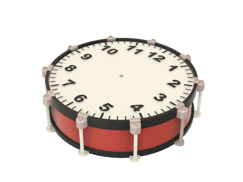
This is an original project I executed for my adult son, Steven. Let’s say he is over 50 in age <G>
Steve is a professional grade percussionist and has been playing drums since he was about 5 years old. (I have pictures!) I might easily say drummer is his alter-ego. It’s not his actual career, but he is about as good and professional as it takes to make it a full time career. Still very active.
So a clock drum was something I could certainly design and gift to Steven, and I was sure he would appreciate.
Parts is Parts
- Details
- Category: Original Design
- Hits: 517
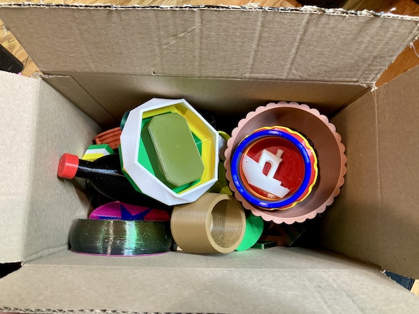
One thing I discovered early-on with 3D printing was a tendency to think all printed items had to be designed and printed as one piece. That is not true or necessary.
Many good projects simply can’t be made as a single print. As a designer, one of my skills is determining the best way to print parts and assemble the project.
The Most Fun
- Details
- Category: Original Design
- Hits: 610
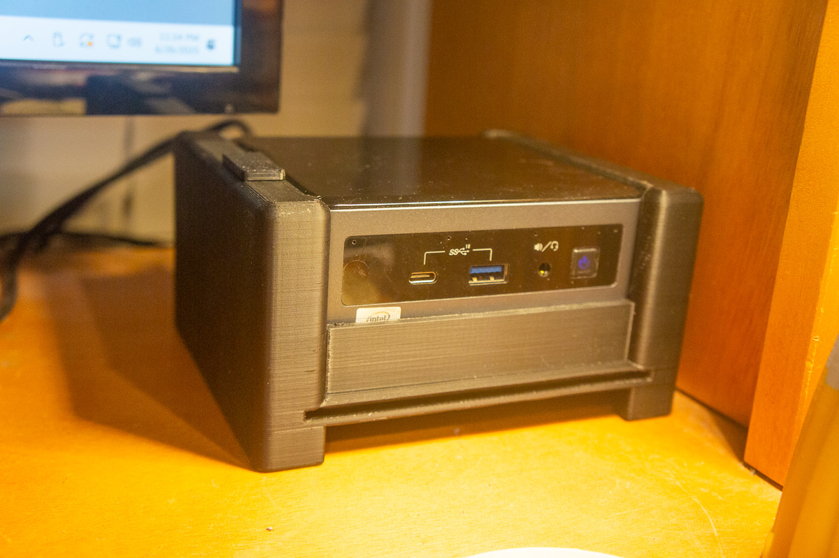
The 3D prints I enjoy the most are the ones designed for a specific need. Not saying I don’t enjoy all the “everyday” prints like containers, vases, boxes and all their variations. If it wasn’t enjoyable, I wouldn’t be doing it.
Page 1 of 4