
- Details
- Category: FDM (Fused Deposition Modeling)
- Hits: 1414
Retraction
The article below is strictly my opinion based on my testing and observations. I present this as an exaple of what works for me. Other opinions may certainly exist and perhaps be more accurate. ~ Dan
 Been doing some additional thinking and testing on FDM printing retraction. There seems to me to be a great lack of information on the operation of very tiny extruders as used in 3D printing. I like to “think” about all the variables and how they affect each other and printing quality.
There is no single answer for every printer and every filament. That’s why a single answer is not suitable for every case.
As a lifelong “systems” problem solver, the very first thing one must do is truly and fully understand the functional operation of the system at hand. It’s called, “knowing exactly what you are looking at.”
Anyone outside the hobby and professional field of 3D printing who has just purchased their first printer (a newbie), are at ground zero on the “know everything” learning curve. After some initial examination of the device, if the person is mechanically inclined, various standard components will look familiar. Like belts, pulleys, motors, switches, knobs; but other specialized parts will be totally new.
In this post, I am focusing on the extruder. The part that becomes very hot where the plastic flows out like thick ink. Hence the comparison to printing. Very HOT printing. Operation of this extruder device is simple, but the science of HOW, will be unfamiliar to a newbie.
I know what an extruder does. But I never owned one other than a hot glue gun or caulking gun. Nothing computer automated. The hot glue gun is a good analogy because it is HOT and doesn’t have a metal plunger.
The extruder is the business end of a small open-ended hydraulic system. Instead of water or hydraulic fluid, the extruder starts out with a solid, heats it to a liquid state, then under controlled (hydraulic) pressure from the filament feed, forces the hot liquid through a small metering device, the nozzle. Just like a hot glue gun.
The Flow
System pressure (the compression or force upon the fluid) and the size of the hole (orifice) are the only factors that determines the flow. There is another factor which is specific gravity (sg) or density, but the system has no automatic control (regulation) of that factor. It is set as a fixed value as part of the slicer flow calculations. Example PLA is about 1.24sg and ABS is about 1.04sg. Enter a density or Specific Gravity setting in the slicer to match the filament is use. Density changes with temperature and material expansion so I have no idea how critical this factor is in slicer calculations, but If there is an entry for it, set it correctly.
Diameter of the filament also has everything to do with volume of flow, as the system must maintain the proper pressure at the nozzle because enough volume is flowing into the system. Said another way; Filament diameter presents a system variable since the software creating the pressure is expecting and requires an available volume (and density) of material which the orifice has been sized to deliver at the system pressure.
This is determined by the length of a specified filament material diameter delivered over time which provides a specific volume. Filament diameter is a factor in determining available volume of flow in properly configured software. Volume is determined by filament diameter and length. Specifically (3.14159 x (Dia/2)^2 ) x Length.
Since there is no automatic pressure regulator or pressure gauge, the print flow volume regulation is dependent on feed length only. The orifice (nozzle) is a fixed variable and can only be changed by installing a new nozzle. However, both wear and accumulated debris in the orifice (hole) will change the effective hole diameter and change flow rate. Nozzles do need to be changed for these reasons.
There is feed (length) rate adjustment and its usually called the Extrusion Multiplier. Printing software determines feed length rate from the nozzle size selected within the software. From there the extrusion multiplier fine tunes the feed length rate and therefore volume and flow. The default is a setting of 1.00 but in most cases less feed is necessary. I have used as low as 0.80 (80%).
That’s why a 2.85MM or 3.00MM filament works just as well as a 1.75MM filament in feeding a 0.4MM nozzle. The filament feeder (the system pump) doesn’t move the filament the same length in both systems. But both systems must put exactly the same force (hydraulic) pressure and material volume into the nozzle when doing the exact same print job.
A hot glue gun is the same hydraulic system as the 3D printer extruder. With a hot glue gun, more squeeze (more pressure) there is more flow. Release the pressure, the flow stops...
The Mechanics
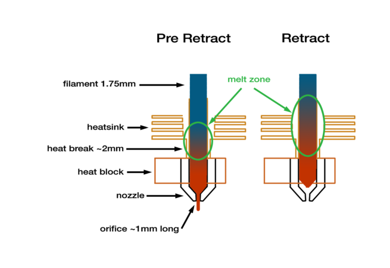
The cold filament is the plunger shaft in 3D printing. The location in the extruder where the filament starts to melt, the semisolid filament expands slightly and forms the “rubbery” plunger seal for the hotter, semi-viscous fluid plastic material ahead of it. A small rubber plug or “blob”.
When changing filaments, one will usually notice a bit of a “blob” on the end of the solid filament removed from the extruder. This blob is the “rubbery” portion of filament that sealed in the heated plastic so that it would only flow out through the nozzle orifice and not up into the cold end. The blob needs to remain very short or will be a source of excessive drag and what is seen as a nozzle plug when the extruder cannot overcome its resistance to movement. This is why most low temp nozzles contain a PTF lining.
Release the pressure to zero in the extruder or the hot glue gun and the flow stops immediately. There is no inertia to the flow as it is a sealed system. Zero pressure, zero flow. Remember that. Only two things control the flow. The size of the hole and the amount of the pressure. If either is zero, there is no flow.
Reduce system pressure to less than zero and the flow through the orifice could reverse.
Basic science explains liquids don’t compress and expand measurably well with pressure, neither do solids. Gas compresses very easily. Liquids expand and contract mostly due to disolved gasses within. Liquids will "flash" to a gas under a vacuum.
In 3D printing there is a function called retraction. It is used to not only stop the flow, but to prevent a term called oozing or dripping from the nozzle. It is a command that reverses the filament feed a measured amount. Usually a few millimeters (more in some systems). Then locks the filament from moving more.
I believe this ooze is caused by two factors. After the feed stops, and before retraction. there is a very short period of pressure bleed down as plastic flows out the nozzle until the pressure in the tiny reservoir of liquid plastic in the extruder behind the nozzle goes toward zero. This is very small amount. But with the feed pressure off, the heater is still on. This heating adds a second source of pressure which is the expansion and out-gassing of the plastic as it is heated. This is why different materials extrude differently. Higher heat thins (reduces the viscosity) and cause more out gassing and expansion.
The reason you can smell the filament when printing (especially ABS) is the out gassing. This is a real factor.
Retraction (reverse feed) is deployed to immediately reduce pressure to zero at the nozzle. It is NOT NECESSARY (or I believe possible) TO “SUCK BACK” the reservoir of melted plastic a given distance in the feed system. The graphic shown is an exaggeration. Gas in the liquid expands.
I know from simple visual observance, the cold (hard) filament does move backwards (retracts). I don’t believe much if any air is sucked into the nozzle. There would be air bubbles in the extruded plastic. What I think is the soft plastic “rubbery” filament blob at the hot/cold junction stretches (thins) a bit with retraction. Like pulling on a rubber band. Certainly, there is air pressure available at that junction. Nature abhors a vacuum and it starts at the blob.
Proof of this theory is the fact that when pulling and changing filament, the melted plastic is not sucked back out of the hot end. It must be purged out through the nozzle until the new filament is seen flowing.
Over retraction will stretch and thin out the filament as thin as the section of filament seen (before and behind the plug blob) when pulling and changing filaments. I also believe over retraction may cause the “plug” region between solid filament and liquid plastic to become larger, adding to higher drag friction in the feed system and slower and lower retraction response. This eventually will appear to be a “plugged nozzle” by the human operator.
It’s not gravity
Experienced users will notice an oozing from the nozzle with no filament feed pressure as the nozzle is originally raised from an OFF or cold state. This is not caused just from running out of the nozzle by gravity or pressure from the feeder. It is the plastic expanding from the continued heating, creating pressure behind the orifice to push the liquid plastic out of the nozzle. It can’t expand up against the feed.
For the plastic to flow from the nozzle by gravity, air would have to flow past the plastic into the nozzle, equally to the volume of the plastic leaving in the other direction. I believe this just doesn’t happen. Look at the ooze stream. It is a blob or full nozzle diameter and does NOT "chug for air".
Consider this…
Turn an open bottle of water upside down and it chugs for air to replace the water leaving. Remember melted plastic is more viscous that plain water. What happens when one turns a Heinz ketchup bottle upside down? Nothing comes out. Air pressure pushes up. A slight negative pressure behind the ketchup is all that is needed to hold it in.
Also consider a sealed bottle of soda. No bubbles. Open and release the pressure. Out comes the gas and can push the liquid out of the bottle. Extream reaction but demonstrates the principle. Gas in and out of solution.
Now let us consider the amount or length of the retraction.
All that is required to stop flow is zero pressure behind the nozzle orifice. As already mentioned, there is no need to “suck plastic back into the nozzle.” Not possible anyway. The extruder is not a vacuum cleaner.
What we must consider is the melted plastic is still expanding and out-gassing a tiny bit creating pressure due extruder heat after we stopped the feed, and the extremely small volume of liquid plastic that may have undergone some volume reduction due to being under compression (very doubtful factor in my opinion) now expands back to atmospheric pressure volume. (I think it is the gas vapors.)
The length of time of being in the “retracted” state is also a factor for bleeding to occur. Long print head travel movements done slowly will permit more time for extruder heating to expand melted plastic (gas) , increasing pressure higher than zero causing ooze.
Rapid moves need to be as fast as possible and as short as possible. Push rapids to the machine design limits without bashing (abusing) the hardware.
Bordon tube style printers are often distained because they are thought to require excessive amounts of retraction. Actually, they don’t require excessive amounts, but more than a close coupled extruder system. The Bordon tube MUST be firmly secured at both the extruder nozzle and the stepper driver. The tube, if properly fixed and secured, never changes length. The Bordon tube must never move in and out of the clamp nut either end during feed/retraction moves. My first Bordon tube printer had clamp nuts that permitted Bordon tube movement. I think this is where the bad reputation was first developed.
This undesired movement at the end clamps is the same as constantly making the Bordon tube longer and shorter while feeding/retracting material.
The Bordon tube is installed as a fixed length pipe. What goes in and out one end is exactly the same at the other end if the pipe is full of a solid material. But the Bordon tube is NOT full. The clearance (slop) between the core material and the wall of the Bordon tube does have an effect on push/pull length. It creates a small bit of flex or “spring” which is why retraction/feed settings are higher in Bordon tube systems.
This is why the retraction setting in print software is a variable. It thankfully is a fixed variable once properly determined (for a particular material) the retraction amount is a constant. But it deserves testing and fine tuning. Over retraction serves no practical advantage and leads to severe wear on the filament at the feed motor as well as the other issues I have mentioned.
Very flexible or soft filament materials may not be suitable for printers with long Bordon tubes for several reasons. Excessive flexing of the filament and a filament surface too soft to withstand the abuse of feed/retraction and the controlled stretching needed for long retractions.
The curve and bending and even vibration of the tube in use in no way changes the length of the tube so has zero effect on retraction length. Bending does increase DRAG within the system. Drag is the single serious problem in Bordon tube feed system.
Drag (friction) must be overcome with the power of the stepper filament drive motor, the drive gear design and plastic filament material strength for withstanding cog teeth of the filament drive.
Grinding away at the side of the plastic filament material is a major cause of feed stoppage or under extruding print failures. This grinding reduces contact of the drive gear to the filament and the roughened diameter from the burrs, debris, and considerable roughness created on the surface of the filament soon creates very high drag in a Bordon tube system. Some operators think they have a nozzle clog (actually very rare unless an extruder overheat has occurred or an overly large end “blob” has formed.
Very rapid retraction is also not necessary. 30mm/s to 50mm/s. Slower is better for the gear drive and filament surface but should not be slower than I list above.
I have had feed friction problem so severe; it was just about all I could do to hand-pull (retract) damaged filament from Bordon tubes. The feed motor had inflicted severe damage on the entire length of the filament between the motor and the extruder head and an unusually large end “blob” had formed from the failure to properly retract. I call it a double whammy!
Excessive retraction length is just one cause of wearing on soft filament. Extreme low first print layer can also cause excessive flow resistance and cause filament grinding by the feeder.
Tiny to small distinct teeth marks on the side of the filament is the ideal. Anything more appearing like “grinding away” is a sign of serious problems and eventual print failures.
The discussion here is about the retraction settings. Bordon tube printers are not an automatic “must be set high” requirement. All that is required is for the nozzle pressure to reach zero.
Use the “coasting” setting to get pressure reduction started before the end of the current flow. Less than a millimeter might be enough to help reduce retraction length several millimeters.
High end 3D FDM printers usually have adjustable tension on the feed gearing for driving or using different material. Yet another variable for the equation for perfect printer setup.
Bottom line. Retraction is a finesse setting. We do not need to rapidly yank back 8mm to 12mm of filament inside the nozzle on every retraction. What we want is the pressure in the nozzle to stay at Zero (actually atmospheric pressure) when we want flow to be stopped. Enough to overcome thermal expansion of the heated material and volatile out-gassing, which are the major contributing factors to oozing.
Understanding what’s going on will lead to proper solutions to printer set-up and elimination of poor printer operational performance.
Another factor to consider.
Long idle no flow periods with nozzle heat held at print temperature (or higher) will cause plugging and flow problems I mentioned previously, the cooking off (out-gassing) of the volatile components in the liquid (melted) plastic. This out-gassing is the main contributor to nozzle oozing while idle. This will eventually lead to carbonization (burning) of the plastic material.
But there is another factor causing nozzle plugging. Especially with lower temperature nozzles containing a PTF lining tube. This tube can deform (melt) with prolonged or high temperature heating. Especially when used with materials like ABS that require high nozzle temperatures. All metal nozzles (no PTF tube) are available for this exact reason.
PTF tubes are used because they create a low friction surface for filament bulging. The little bulge between the hot and cold regions that creates the plunger disk.
I mentioned a controlled bit of over retraction also stretches and thins the filament. This helps prevent large end plug bulges from forming, which plug nozzle flow. I think this is a major cause for perceived plugged nozzles.
Overreaction is sometimes used in multi-filament feed into a single nozzle. My tests show this is not usually needed. The idle filament is not retracted "out of the way" when changing color. It remains in place while the excess is purged by the next color.
Any dual print head (tandom or IDEX) that is going to sit idle needs a few extra mm of retraction. A controlled reduction of temperature is good practice if possible.
Summary
I believe most of the blame for “bad filament” plugging nozzles is this “secrete behavior” of the material flow and stretch behavior between the hot and cold ends of the extruder. A part of the hidden retraction mechanics inside the extruder.
I am now running nozzles for hundreds of prints without problems. I usually wear them out and change them because of end drag and not from becoming plugged.
An idle heated nozzle is a problem waiting to attack, so I never hold an extruder at printing temperature when not extruding.
Knowing the details helps solve problems before they occur.
- Details
- Category: FDM (Fused Deposition Modeling)
- Hits: 1449
 The Dimensional Print Studio has joined the ranks of multi-color three-dimensional printing. This is with the FDM (Fused Deposition Modeling) process using plastic extruded filament. The printer obtained, a GeeeTech A20M (the “M” is for multicolor) printer.
The A20M uses two filaments and combines the feeds into a single nozzle. This permits blending (sort of) of the two filaments. The colors don’t mix and when fed to the nozzle together, come out the 0.04MM tip side by side in proportion to the feed. Like stripe toothpaste in a tube. 30/70, 50/50, 70/30 it will show in the print.
Much two-color printing is done with a nozzle for each color. No blending is possible. Using a single nozzle, requires a purge area to pump out the old color before printing (100%) with the new color. A “purge pillar” is built up layer by layer alongside the intended print for purging. This pillar is “wasted” and thrown away and is a concern for some stingy printer owners.
Two color printing can take up to twice as long as single color printing. So, two color printing is not popular for many folks. Especially if they have an extreme obsession or phobia about “wasting” material changing colors.
Waste is a product of all forms of crafting and manufacturing. Does a woodcarver obsess over the 50% waste of material in the form of shavings and chips when carving a figure? Did Michael Angelo obsess over the “wasted marble” when carving David? I think NOT!
Not sorry about the rant above. I’ve just heard about wasting material too many times in 3D printing…
The rewards of having color options are quite enjoyable. For me it has moved my printing further in the realm of an art form, without the need for priming and painting. Or printing multiple pieces to assemble. That will go on, but it is fun to design and see it produced in a single print.
Here are some examples of my first prints. Surely there will be much more to come.
 |
 |
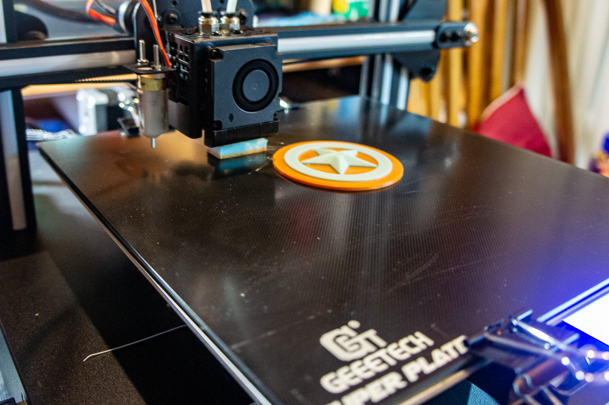
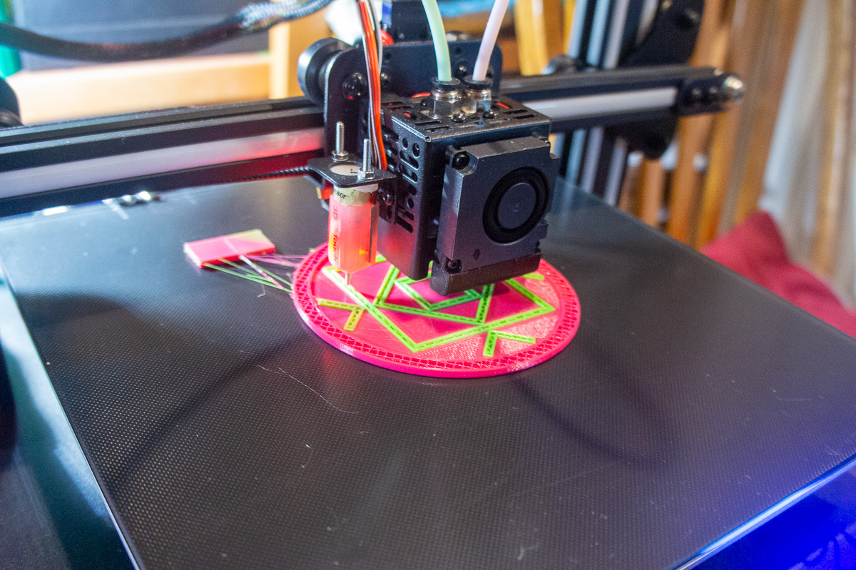
| This is my first print in two color. It is my own design created in Fusion 360. | The A20M came with a mouse pad!. The rectangle is the purge piliar required to clear color from the single nozzle. |
 |
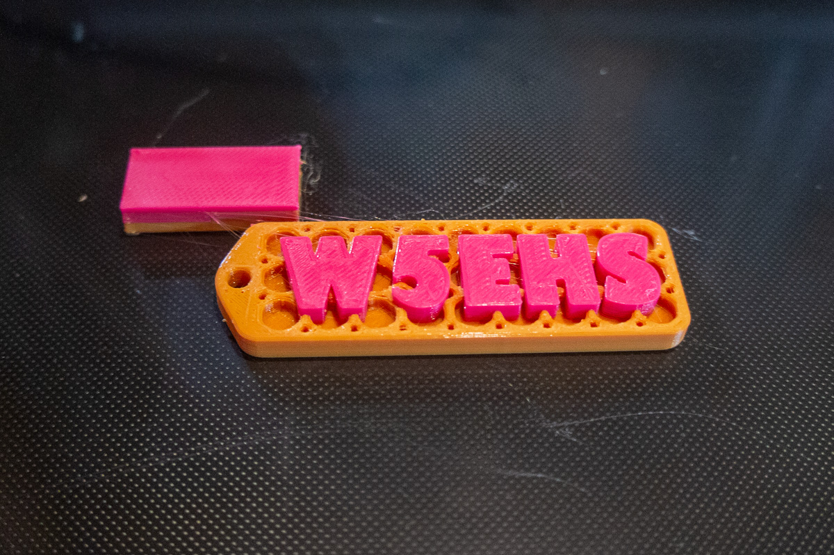 |
| This is a key fob I printed with different color loaded. | The W5EHS is my amateur (ham) radio call sign |
 |
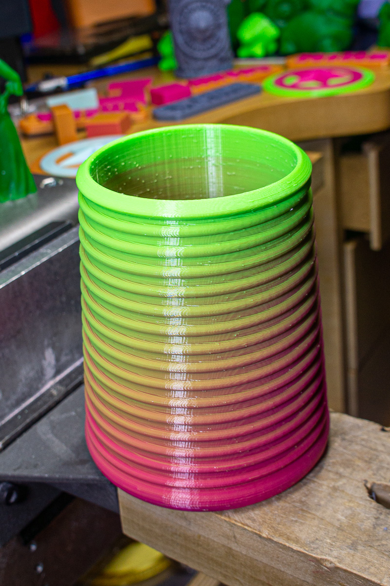 |
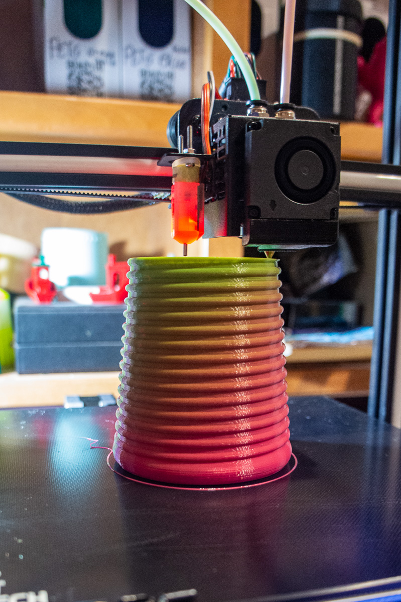
| This is a process of blending two colors into a single nozzle printer. | Because the colors don't truely mix, the pink rises higher on the right side and the green is lower on the left. |
 |
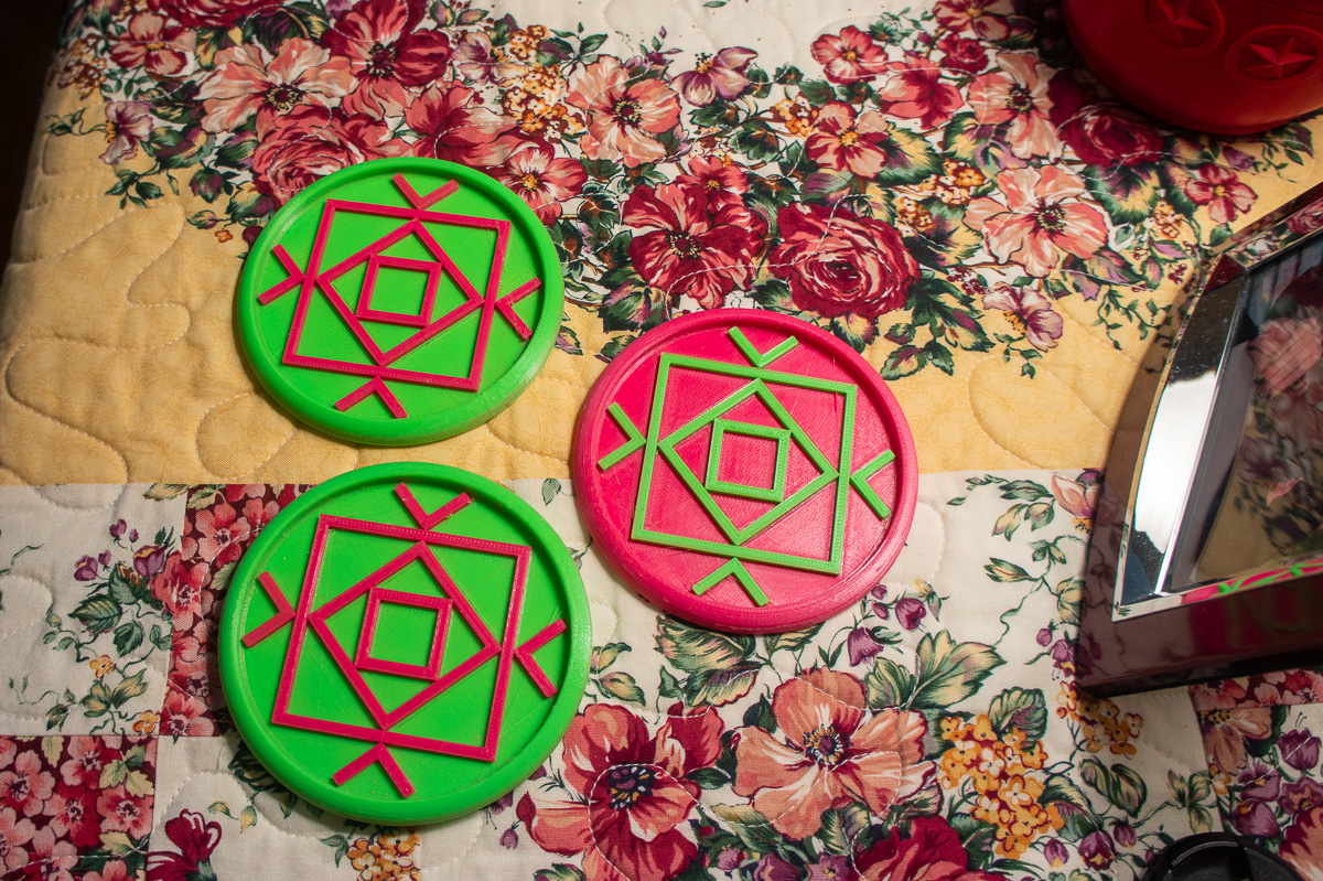 |
| Quilting square coaster I designed in single color has been updated for 2 color printing. | Same pattern, just switch colors when slicing. |
 |
 |
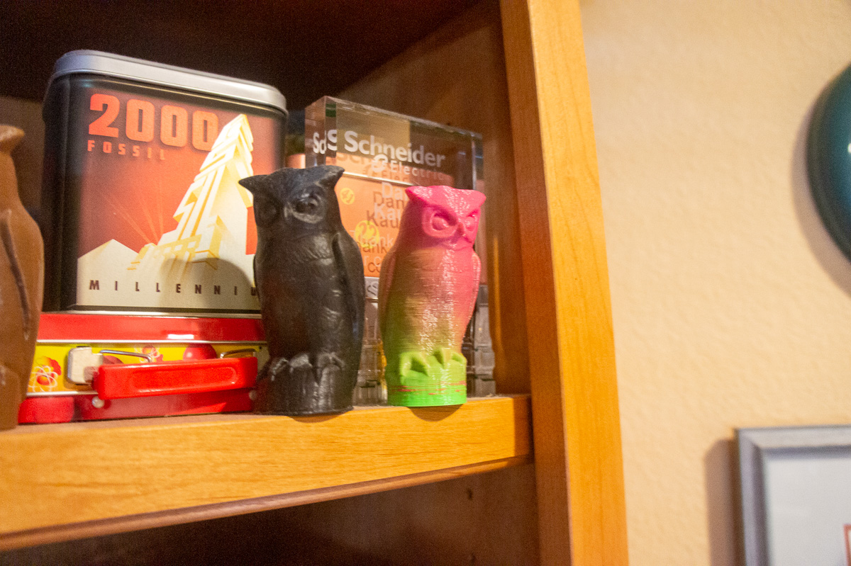
| Here is a blended color FDM owl nect to a DLP resin printed owl. | Another blended color print. This time red to grey |
- Details
- Category: FDM (Fused Deposition Modeling)
- Hits: 1394
 New PETG print after nozzle change.Been messing around for two days trying to figure out how to get decent PETG prints off my A/C Delta printer. Then I remembered my PLA prints were looking a bit crappy for quite a while, too. But PETG is a far fussier material than PLA, so I was thinking, doing a little mental math… 2+2=3.14159265…
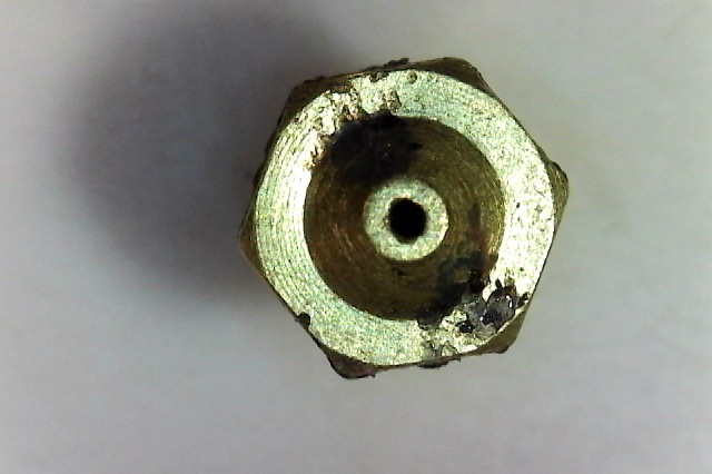
Then I looked really close to the printing going on with the top layers on the current test PETG print I was running. “Dang! That nozzle tip looks awful short!” I said to myself. It’s drawing the shoulder of the nozzle across the top of the print!!
AH… 2+2=4!! Now the pie is on my face! The tip of the nozzle is worn off. That hole isn’t 0.4 MM. It looks like at least 1.0 MM!!!!
Of course, I couldn’t see that at that moment, but it was obvious I needed to change out the nozzle.
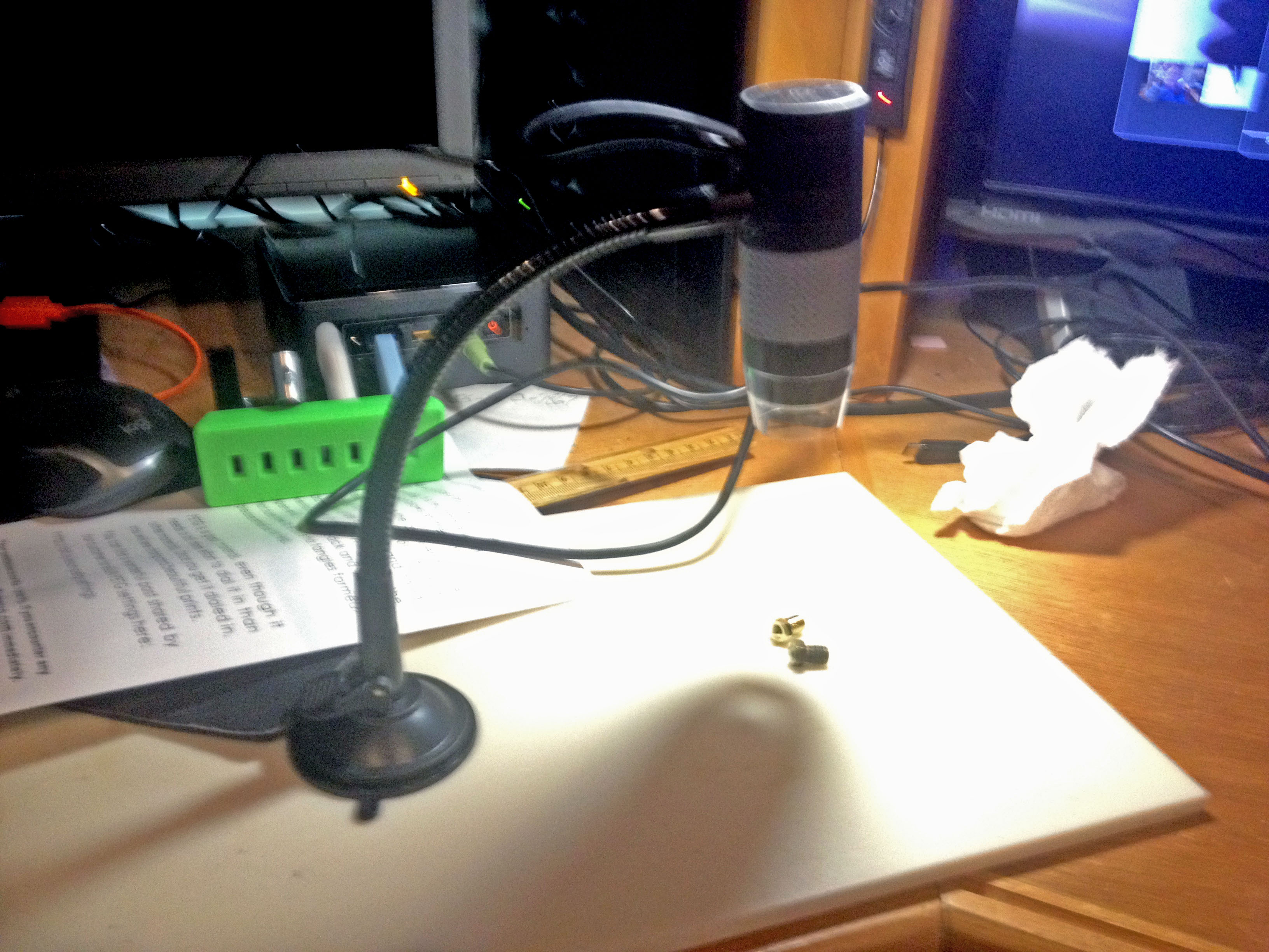
With the (very) old nozzle removed, I was able to examine it under my photo microscope and grab these pictures.
 The new on the right the old on the left. Think there was a problem there.
Lesson learned… Just because it isn’t plugged, doesn’t mean it’s still good… DUH?!
Yeah, that old nozzle probably made at LEAST 100 good prints or more. The quality was dropping but the present PETG really drove the issue home. I’ll be changing nozzles a bit more often now I see how they wear.
I was wondering about how nozzles change with time as I was doing my test prints. I have read the claim that flow through them with stuff like carbon fiber wear the hole bigger, but it looks to me that wear off the end is also a big problem. It depends on if the hole is tapered inside or has a fairly long parallel wall hole. This may be a combination of both.
I also read that some nozzles carbon up inside from overheating and the effective hole diameter gets smaller. I bought an expensive steel nozzle months ago and have never installed it. Not even now. I have run a lot of wood PLA through the old nozzle, but it says wood does not wear out the nozzle. That old nozzle has seen PLA. ABS, wood, and PETG. After a good purge, they all flowed fine.
Months ago, when I was playing with printing test parts for a U-Build-It 3D printer, the same spool PETG was not printing quite like I expected. I just blamed it on poor S3D settings. It was probably the point when I should (could) have changed out the nozzle. That old one was in there forever even then.
 |
 |
| A camera microscope is a handy tool for nozzle inspection and photo capture. | The left is the new nozzle. The right was exactly the same, now with at least a 4X bigger hole! |
 |
 |
Now wiser than I was yesterday, this old dog can still learn a few tricks…
- Details
- Category: FDM (Fused Deposition Modeling)
- Hits: 2364
 Just kicking back and playing with the Cetus (MamaCetus) printer. I had noticed there is now a Mk3 version available that could be modified to run g-code directly from 3rd party slicer sofware. (See previous post.) I have always been able to do that with MamaCetus (indirectly)
Transferring the g-code file from say, SImplify3D to UPStudio is not a hard task. One doesn't see the anamation of the Simplify 3D when printing via USB, but there is also no anamation when using UPStudio.
It had been a while since I ran g-code through UPStudio to MamaCetus. I decided I should get back into the practice as it looks like there is a lot of outside g-code going to be run on the new Cetus.
I remembered my printing results were excellent in the past but things change since then. The UPStudio was updated, as was Simplify3D. I also made bed changes to MamaCetus and nozzle heights would have to be reset in Simplify3D.
 The pictures show the printing is as good as ever. It's what I refer as Junque Item printing but that is OK! These cube puzzles were sliced in Simplify3D and fed to MamaCetus via UPStudio. The layer height is 100 microns (0.100 MM) The quality is excellent for FDM printing.
Hard to beat the linear rail/bearing axii quality on MamaCetus.
- Details
- Category: FDM (Fused Deposition Modeling)
- Hits: 820
MamaCetus
I have a 3D printer made by Tiertime called a CETUS. I named mine MamaCetus, as a pun on the Latino slang term mamacita meaning hot babe. (sexy woman). The printer is certainly very hot and might be considered sexy by some 3D printer nerds (Me?) Hmmm...
OK. In any case, Tiertime just revealed a new version (MKIII or MK3). It has all the same general features of versions 1 and 2 but some interesting detail improvements. MamaCetus is a MK2.
Mechanical end switches for homing. They used a motor stall sensor in the previous versions. Switches are more positive and repeatable for setting home position.
New accessory board available for heated bed and auto Z / bed leveling sensor. That’s three different and separate accessories but the board is necessary for operation of the other two.

An optional 220 watt (!!) What! Power supply is available to help out the heated bed option. Yowza! Plenty of extra power. Note: the wattage of the PS over what is needed is not a problem (unless something shorts out.) My original PS says 19 volts at 6.32 amps which is 120 watts. 100 more watts for the heated bed is good.
Print head hot-end upgraded (V2) to use nozzles suitable for almost any printable filament available. Hardened steel nozzles available. Compatible with older nozzles.
A plug in processor will be available for direct G-Code operation with virtually all 3rd party slicer programs like Cura and Simplify3D and others.
Color touch screen controller is also in the works.
All the add-ins above are extra cost, so the customer can be selective of if or when they want to update for the added features.
I currently run G-Code produced from Simplify3D on my MamaCetus. I am pleased the new processor or co-processor will permit direct connection to 3rd party slicers. This is what Tiertime claims! That could be sweet. However, when installed, the Cetus printer will NOT be compatible with UP Studio, heated bed and bed leveling. Oops!
I’m not ready for an upgrade to the same size printer I have. However, the Cetus does produce excellent quality prints because of its linear rail construction.
- Details
- Category: FDM (Fused Deposition Modeling)
- Hits: 1555
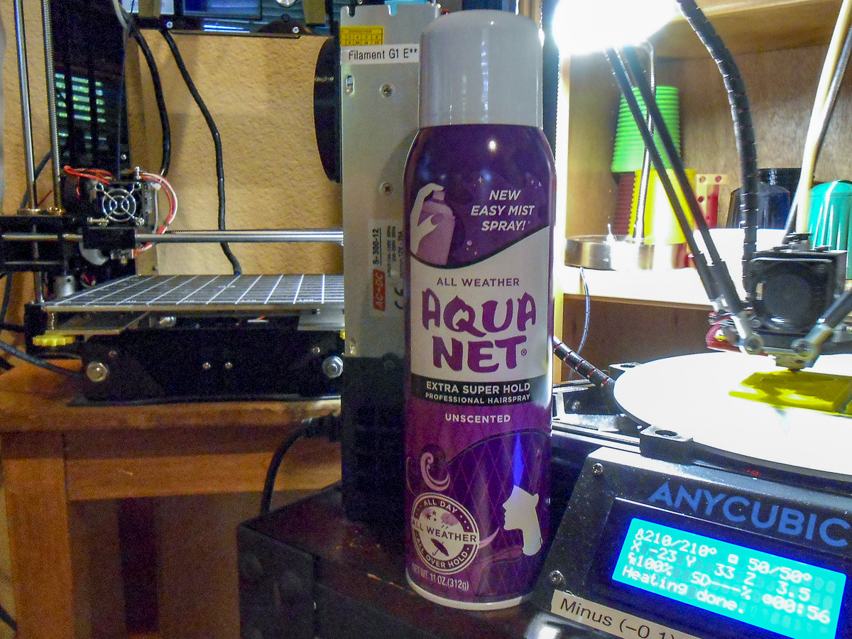
Glass Print Bed with Aqua Net
I put a round glass print surface on both Delta style printers I have (had), I sold the smaller one. I installed PEI or Buildtak (like) surface on top of the glass on both. I used the glass to assure a perfectly flat printing surface.
I didn’t like the concept of rubbing a glue stick on the surface to get a print to stick. I considered hair spray with the same disdain. But I hadn’t given either method much of a try. I did try a glue stick several times, but considered it a real and unnecessary mess.
But Buildtak was tearing-up with some regularity. Some material like PETG sticks too well. The real mess was getting Buildtak off the glass for the next application. A heat gun (like stripping paint) does a good (but hot) job. Buildtak changes were getting expensive as well.
PEI was also a hit and miss material. When it works, it works well. But then it will start loosing its grip on things…
All stick-on sheets suffer from air pockets. Perhaps the 3M glue gases-off a bit after repeated heatings. I can’t prove that, but I know bubbles form long AFTER initial installation. That’s where a tear-out hoie develops from pulling off prints.
I watched a video on You-tube where a fellow was praising the use of hairspray. Since I had not given it a fair trial, I decided to give it a go. My wife let me use some of her hair spray.
It was a highly perfumed, water based lacquer, for which I can hardly stand the smell, but it worked very well as a “stick-um” for 3D prints. Both PETG and PLA. But it was very hard to wash of the glass, requiring vigerous scrubbing, soap, and hot water.
The video recommended the cheapest “Aqua Net” superhold to be found. My wife found the non-scented variety in 11 ounce cans for $2.00 a can. She bought me 3, which looks like a lifetime supply.
I discovered the Aqua Net is far superior for printing to the variety my wife uses on her hair. No smell what-so-ever and a super flat dry out on the glass. It also lasts through multiple prints, where the perfumed brand pealed off with each print. I don't know how good Aqua Net is for hair use, but printing use it is perfect. And it washes off the glass very easily and cleanly with cold water. It couldn’t be better.
The prints come off the bed with a perfectly smooth contact surface. Rafts are usually not required. The prints will “pop” off the surface if you let the bed cool down. But it works with a non-heated bed just as well.
Aqua Net is my new standard for bed adhesion in FDM 3D printing. Why did I wait so long?